


432-0012-05-00 Flir M500 Thermal Camera System, 2 Axis Gyro, ULR-Zoom, LED Spotlight, 30Hz
$340,971.40 Inc. GST
432-0012-05-00 Flir M500 Thermal Camera System, 2 Axis Gyro, ULR-Zoom, LED Spotlight, 30Hz
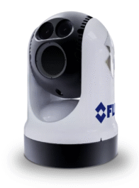
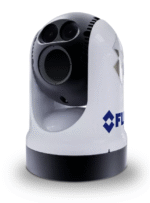
High resolution marine thermal camera with pan and tilt, 2-axis gyro stabilization, ultra long-range zoom, ultra low-light camera, and LED spotlight.
M500 Thermal Detection Ranges
- Human (Detect Human Sized Target) – 2.0nm (3625m)
- Vessel (Detect a 30-foot Vessel) – 5.0nm (9260m)
- NATO Target (2.3m x 2.3m @50%) – 3.5nm (6480m)
Maximum-Performance Multi-Sensor Camera
The M500 stands as the pinnacle of commercially available FLIR marine thermal cameras for maritime applications. Its mid-wave detector offers double the image sensitivity compared to long-wave infrared cameras, enhancing range performance by 35%. With superior performance in fog and other atmospheric conditions, cooled mid-wave sensors surpass long-wave thermal cameras. Additionally, the M500’s internal gyro stabilization ensures a stable view even in turbulent seas.
Positive Target Identification – M400 and M400XR feature a tight LED spotlight for identifying targets or inspecting incident scenes.
432-0012-05-00 Included in this Pack
- Camera Unit: M500, 30Hz Refresh Rate
- Weather Seal: Riser base-seal
- Weather Seal: Camera seal
- 500-0398-10 JCU II, Joystick Control Unit
- 4141042 5-port PoE+ Ethernet Switch
- 308-0263-01-00 – Power cable – right angle, 12 AWG, 1 m
- 308-0261-01-00 – Ethernet cable – right angle to RJ45, 1 m
- 4115028 – RJ45 waterproof enclosure coupler
- 308-0265-01-00 – AV and serial cable – right angle, 1 m
- 308-0267-00 – HD-SDI cable, 1m
- 4142057 – HD-SDI isolation transformer
- Installation and User Documentation Pack
INSTALLATION NOTE – You will need to supply the following items depending on planned installation:
- For Top Down Riser—Six (6) M8 stainless steel bolts and washers to secure the top down riser after the camera is attached—bolt length depends on mounting platform thickness. Recommended: M8 socket head cap screws, or 5/16” – 18 socket head cap screws, or 5/16” – 18 hex head sheet metal screws type 316 stainless steel Apply thread locker (Loctite 262 or equivalent)
- One or more multi-function displays (MFD) or other analog or digital video display devices
- Coaxial RG6 video cable to customer-supplied analog video monitors
- Coaxial RG6 video cable to customer-supplied HD-SDI digital video monitors
- Ethernet cables to connect the M500 and the JCU II to the PoE Ethernet switch, 8-conductor T568B
- Ethernet cables to connect to the ship’s Ethernet port, 8-conductor T568B
- Miscellaneous electrical hardware, connectors, and tools
M500 Components:
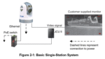
• Main camera body, also known as the pan/tilt camera unit
• Joystick Control Unit (JCU II), compatible with the MU, MV, M400, and M500 camera systems
• Ethernet switch with power over Ethernet (PoE) to power the JCU II and network to the camera
• Analog and/or digital video monitors (customer supplied)
• Personal computer (PC) to control and configure the system (customer supplied) The M500 camera body and JCU II are network devices.
In some installations, additional M500 cameras and/or additional JCU II may also be used. The camera body’s pan/tilt mechanism allows the operator to rotate 360° in azimuth, tilt +/– 90° in elevation.
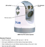
The camera body houses the two cameras, and the LED spotlight.
The cyrocooler requires approximately six minutes to cool the thermal sensor before IR video is usable.
Note: If the IR video is not required as an instant on feature, use the cooler On/Off control to lower power usage and extend the cooler lifetime. See “IR cooler:” on page 28.
The JCU II is the primary control for the camera. The JCU II is used to wake the system or put it in standby, select the active camera, operate the pan and tilt movement of the camera, zoom the active camera, control the M500 modes and features, and configure the system settings by means of OSD menus. The JCU II has buttons, an LCD display, and the joystick. The joystick can be moved left and right or forward and back, and rotated in either direction. “M500 Joystick Control Unit” on page 16 describes the functions of the JCU II in detail.
The M500 uses on-screen icons to indicate the camera position (azimuth and elevation) and various system settings that have been enabled. These symbols are introduced in “Thermal Video Display” on page 11 and are further explained throughout this manual in the discussion of related functions.
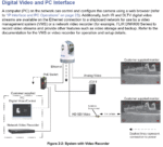
Multiple Cameras, Joysticks, and Other Devices: More than one JCU II can be used to control the camera, and more than one display can be used to view the video.
A personal computer (PC) on the same network as the camera, can use a web browser to view video, control, and configure the system. The camera’s web server uses password protected accounts to control access to camera functions. Using a PC is described in the M500 Installation Guide.
Also, a single JCU II can be used to select and control more than one camera. In this case, a menu on the JCU II lists available cameras. In the LCD display of the JCU II, the name of the currently selected camera is displayed. When more than one JCU II is installed in the network, a camera will respond to commands from any JCU II that has the camera selected. Typically, a JCU II and a video monitor are mounted in close physical proximity, as a pair, so you can immediately see the changes on the video screen when you use the JCU II to change the camera position (pan or tilt).
Optional Accessories, available to purchase, but may or may not be included in this Pack
- 308-0260-01-00 Cable – Ethernet to RJ45, 1 m
- 308-0262-01-00 Power Cable – 12 AWG, 1 m 308-0264-01-00 Cable – AV and serial, 1 m
- 4141864 Cable – HD/SDI, 100 ft
- 308-0251-30-00 Cable – Ethernet to RJ45, 100 ft, LSZH
- 308-0252-30-00 Cable – Ethernet, RA to RJ45, 100 ft, LSZH
- 308-0253-30-00 Cable – Power, 12 AWG, 100 ft, LSZH
- 308-0254-30-00 Cable – Power, right angle, 12 AWG, 100 ft, LSZH
- 308-0255-30-00 Cable – AV and serial, 100 ft, LSZH
- 308-0256-30-00 Cable – AV and serial right angle, 100 ft, LSZH
- JCU-1 (500-0385-00)
- JCU-2 (500-0398-10)
- JCU-3 (A80510)
- JCU-4 (E70695)
Standard Features
- Cryogenically cooled thermal camera with On/Off cooler control, 14x continuous optical zoom
- HD visible-light camera, 30x continuous optical zoom
- High intensity LED spotlight
- Active gyro-stabilization
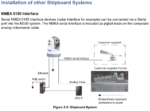
- Radar integration to follow specific radar targets (NMEA 0183 serial communications)
- Dual, independent H.264 network video streams
- HD-SDI (Serial data interface)
NOTE: The Analog Video, Thermal Camera, HD visible-light camera, and spotlight are aligned to view or illuminate a target for quick identification providing enhanced navigational abilities in a variety of conditions.
Premium Long Range Thermal Vision
High-sensitivity mid-wave detector delivers superior image quality and enables long-range object recognition, while the M500’s video tracking feature allows automatic following of a selected target using either thermal or visible cameras.
Additionally, the M500 includes a HD color camera with 30x optical zoom and a low-light camera with 12x electronic zoom, ensuring detailed imaging in various lighting conditions.
2-Axis Stabilization – Navigate with a steady view in rough seas. Vertical stabilization compensates for vessel pitch and horizontal stabilization maintains the M500’s field of view on a selected bearing.
Long Range Thermal – A cryogenically cooled mid-wave thermal sensor delivers extra long range target detection.
2-Camera Payloads – High Resolution Thermal + an Ultra Low Light Visible Camera.
Chartplotter Compatible
FLIR M-Series cameras are designed to integrate seamlessly with chartplotters and multi-function display from Furuno, Garmin, Raymarine and Simrad. View the thermal image on your chartplotter display and control the camera’s pan and tilt with your chartplotter’s touchscreen.
FLIR M500 – SPECIFICATIONS
| Thermal Camera | |
|---|---|
| Field of View | Optical 28° x 21° WFOV to 2° x 1.5° NFOV |
| Video Refresh Rate | 25 Hz (PAL) / 30 Hz (NTSC) |
| Focal Length | 19mm (Wide) to 275mm (Narrow) |
| Optical Zoom | 1x to 14x (continuous) |
| Digital Zoom | 4x Continuous |
| Detector Type | Cooled MWIR InSb 640×512 Focal Plane Array |
| Visible Camera | |
|---|---|
| Detector Type | 1/2.8” CMOS |
| Lines of Resolution | Up to 1920 x 1080 @ 30fps |
| Minimum Illumination | Low Light Setting ON: 0.006 lux / Low Light Setting OFF: 0.1 lux |
| Optical Zoom | 30x |
| Digital Zoom | 12x |
| Focal Length | 129 mm to 4.3 mm |
| Field of View | 63.7° x 35.8° WFOV to 2.3° x 1.29° NFOV |
| Spotlight | |
|---|---|
| Type, Lumens, Beamº | LED, 580 Lumens, 5° Divergence Angle |
| System | |
|---|---|
| Gyro Stabilized | Yes |
| Video Tracking | Yes |
| Pan/Tilt Adjustment Range | 360° Continuous Pan,± 90° Tilt |
| Analog Video Output | NTSC or PAL, 30 Hz or <9 Hz |
| Analog Video Connector Types | F-type BNC with BNC-to-RCA adapter included for video out |
| Network Video Output | Four, Independent H.264 Network Video Streams |
| HD-SDI Lossless Video Output | Yes |
| Power Requirements | 12-24V DC |
| Power Consumption | 250 W (max w/heaters) |
| Environmental | |
|---|---|
| Operating Temperature Range | -13°F to +131°F (-25°C to +55°C) |
| Storage Temperature Range | -56° F to + 176°F (-50°C to +80°C) |
| Automatic Window Defrost | Standard at Power-Up |
| Sand/Dust Ingress | Mil-Std-810E |
| Water Ingress | IPX6 |
| Shock | 15 g vertical, 9 g horizontal |
| Vibration | IEC 60945; MIL-STD-810E |
| Lightning Protection | Standard |
| Salt Mist | IEC60945 |
| Wind | 100 knot (115.2 mph) |
| EMI | IEC 60945 |
| Physical | |
|---|---|
| Weight | 32 lb (14.5 kg) |
| Size | Camera: 10.8” (273mm) x 15.7” (398mm) / Camera with Top-Down Riser: 12.8” (324mm) x 18.1” (459mm) |
| Range | |
|---|---|
| Detect a 30-foot Vessel | 5.0nm (9260m) |
| NATO Target 2.3m x 2.3m @50% | 3.5nm (6480m) |
| Detect Human Sized Target | 2.0nm (3625m) |